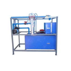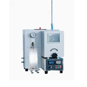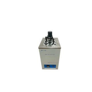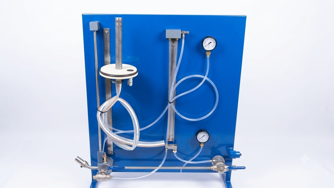
Description
| Component Group | Specification Details | Primary Function |
| Support Panel | Vertically mounted steel plate with a corrosion-resistant blue powder-coating. | Holds structural test lines, pressure instrumentation, and routing tubes securely. |
| Constant Head Tank | Small, transparent/white cylindrical vessel mounted on the upper left rail track. Height is adjustable. | Guarantees a stable, constant inlet pressure head which is essential for stable laminar flow testing. |
| Pressure Instrumentation | Dual Dial Gauges / Differential Manometers mounted directly to the board. | Measures the exact pressure drop (Δ P) or fluid head difference (hfh sub fℎ) between test points. |
| Test Circuit Sections | Linear metal tube section aligned alongside a vertical calibration metric. | Serves as the fixed-length (L) and fixed-inner-diameter (D) path where flow resistance takes place. |
| Flow Controls | Manual Control Valves (ball/needle types) positioned at the bottom baseline manifold. | Modulates fluid volume to shift experiments smoothly between low (laminar) and high (turbulent) Reynolds numbers. |
| Interconnecting Lines | Flexible, high-grade transparent PVC tubing paired with leak-proof quick-connect couplings. | Routes water from source modules to the target testing areas while keeping visual track of air pockets. |
Standard Educational Experiments
- Friction Factor Analysis: Calculating the Darcy friction factor (f) relative to the flow’s velocity profile.
- Flow Regime Boundary Identification: Visually and mathematically identifying the critical Reynolds number where laminar flow destabilizes into turbulent flow.
- Moody Diagram Verification: Plotting the correlation between pipe wall roughness factor, Reynolds number, and energy loss gradient.