Description
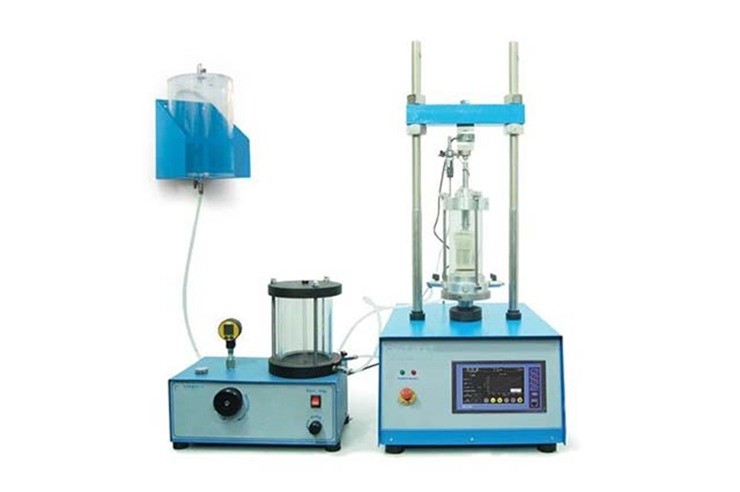
- Load Frame Structure: The rigid, blue-and-silver dual-column structural frame supports the vertical drive mechanism.
- Triaxial Cell: Placed in the center, this transparent cylindrical chamber encloses a soil specimen wrapped in an impermeable membrane. The chamber is filled with water to apply standard confining pressure.
- Axial Load System: The stepper-motor-driven crosshead applies controlled vertical mechanical stress (deviator stress) to test the soil specimen’s shear strength until it reaches failure.
Controls +1
- Integrated Control Panel: The base features an integrated touch-screen LCD graphical interface alongside safety mechanisms like an emergency stop button. This setup enables automated, closed-loop control over loading speeds and data logging.
System Context
The complete assembly shown in the image represents a modular triaxial configuration. The auxiliary setup to the left includes an Advanced Pressure Volume Controller (APVC) (with its transparent bladder cylinders) and a de-aired water tank. Together, these modules allow technicians to accurately simulate real-world site conditions, evaluate total and effective stress parameters, and execute standard testing regimens—specifically Unconsolidated Undrained (UU), Consolidated Undrained (CU), and Consolidated Drained (CD) tests