Description
The Electrical Wiring Trainer Board should consist of below:
Electrical Training System: Provide available electrical components and interconnect in different configurations.
Acquire the basic knowledge on electrical engineering, installations and electrical measurements.
Study the means to check the main laws and principles.
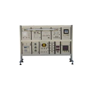
Component symbols and electrical diagrams are represented on the front panel.
The symbols and electrical diagrams of each component are clearly represented on the front panel.
The connections are eased by 4mm terminals and cables of different colors. The power supplies are included with extra low safety voltage.
General switch, fuse and signaling lamp:
Safety single-phase transformer 115-230V/ 6-12-24 VAC-1 A Fuse-holder with fuse type 6×30-1A
Moving iron ammeter with range: 0.5-1A Moving iron voltmeter with range: 25 V
Resistors of different values (2, 4, 8, 16, 31.5, 63, 250, 500, 1000, 2000) linear rheostat 100/25W
Diodes 6A-100V
Lamp-holder with 24-V signaling lamp 24-Vac buzzer Electrolytic capacitor, 100 F25Vdc Electrolytic capacitors, 500 F25Vdc Inductances 60 mH 0.5 A
Electrical Sequence Trainer: Hands-on electrical sequence practices using various electrical components with electric contact. Simulates real life components and power source that is being
used in the field Ensures safety using insulated connection cables and insulated connection terminals
Experimental Contents:
Basic circuit Logic circuit
Self-holding circuit Timer circuit Priority circuit Detection circuit Lamp and alarm circuit Motor
operational circuit Reactor-driving circuit Jog circuit
Forward & reverse circuit Delay operation circuit Time activation circuit Y-Δ operational circuit
Earth leakage circuit breaker (ELCB): 1 Nos Rated voltage: AC 220V 60Hz
Rated current: 30A
Rated residual current: 30mA Electronic contactor (5a2b): 3 Nos
Contact capacity: AC 240V/18A / 4.5kW Auxiliary contact capacity: AC 240V 3A Electronic overload relay (EOCR, 1/2HP): 1 Nos Internal CT (sensor): 3-CT (tunnel type)
Current setting: 0.3 ~ 1.5A Trip time setting: 0 ~ 30 sec.
Contact capacity: AC 250V 3A (Resistive load) Relay (4C):2 Nos
Contact capacity: AC 220V 3A (Resistive load) Timer (30 seconds): 1Nos Operational method: ON delay
Output contact capacity: AC 220V 1.5A (Resistive load) Flicker timer (6 seconds): 1 Nos Operational method: ON Start
Output contact capacity: AC 220V 2.5A (Resistive load) 3-phase induction motor: 1 Nos Operating voltage: 3-phase AC 220V / 380V / 25W
Type of motor: Squirrel cage rotor, 4-pole and Y-Δ Starting Rotary disc: Rotational speed detection type
Electronic brake: Intensity control function Proximity sensor: 1Nos Digital counter: 1Nos
DC power supply: 1ea Output: DC 24V 1A (fuse) Lamp: 4 Nos Buzzer: 1 Nos Push button: 4 Nos
Toggle switch (1a1b): 2 Nos Fuse and fuse holder: 2 Nos Supports angle adjustment: 1 Nos
STANDARD ACCESSORIES:
Power cord: 1Nos
4ø insulated connection cable: 1set User’s guide & experimental manual: 1set
Digital Multifunctional Meter:
Showing electrical wiring tips on the LCD screen User-defined backlight setting (10/20/30 sec.)
±0.2% precision
Fast and accurate response rate Effective measurement of RMS values
Indication of a measured data in the minimum, maximum and average values Earth resistance measurement in two points and three points
Automatic Power OFF function Bluetooth communication
Displays the connection of reed wires AUTO/MANUAL range selection Initiation of calibration by pressing a key button ACV: 0.0-750.0V True RMS DCV: 0.0-999.9V
Insulation resistance (MEG Ω):
DC 1000V: 0.00MΩ ~ 9.99MΩ, 10.00MΩ ~ 99.
99MΩ