
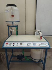
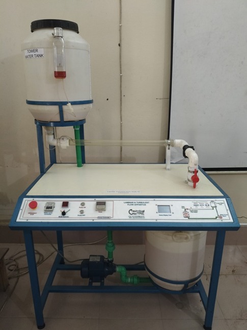
Description
- Upper Fluid Reservoir (Tower Water Tank): The large white cylindrical plastic container positioned high up on the left side. It serves as a constant-head tank to supply water to the test section. A smaller translucent container is attached to its front, which functions as a dye reservoir to inject colored fluid into the stream.
- Transparent Test Pipe: The horizontal clear acrylic tube running across the middle of the table benchtop. This is where fluid transition happens; injecting a narrow stream of dye into this section allows students to visually distinguish between smooth parallel flow layers (laminar) and chaotic mixing patterns (turbulent).
- Control Valve: The red handle valve positioned at the right-hand junction of the plumbing. This enables manual adjustment of the flow rate and fluid velocity running through the system. Lower Storage Sump Tank: The large white plastic bucket situated beneath the main table frame on the right side. It collects the discharged water that completes the circuit.
- Electric Pump: The dark blue centrifugal pump installed next to the lower sump tank. It draws water back up from the storage tank into the tower reservoir, creating a self-contained, closed-loop water circuit.
- Integrated Instrumentation Panel: The control board lining the front rim of the benchtop table. It features electrical toggles, buttons (including a red emergency stop button), and display readouts to manage the pump speed and monitor variables during experiments.


